Showing posts with label esp8266. Show all posts

Thursday, 8 February 2018

The all-you-can-possibly-want ESP8266 dev board


All-in-one ESP8266 module

I did a very simple 5-minute example project with this board. The video will be available shortly.
The video is available here now!

Overview

The somewhat unwieldly name "Wemos® D1 Esp-Wroom-02 Motherboard ESP8266 Mini-WiFi NodeMCU Module ESP 8266+18650 Battery+0.96 OLED" betrays a very complete ESP8266 development module, that boasts a load of features:
  • USB2Serial bridge (Silicon Labs CP210x USB to UART Bridge)
    If your PC does not automatically detect the driver, you find it here.
  • Power switch
  • LiIon charge circuit
  • 18650 battery holder
    Beware: the holder is too short for my favourite protected 18650 cells. These INR cells should fit instead.
  • "Wemos" labelled ESP-12F ESP8266 module. It does not look like a WROOM-02, though.
  • SSD1306 OLED display
  • 4-way + push "joystick"

Bells and whistles
The Wemos product page does not list a module like that, so it might not be their product at all.
The advertised product name:
Wemos D1 Esp-Wroom-02 Motherboard ESP8266 Mini-WiFi NodeMCU Module ESP 8266+18650 Battery+0.96 OLED does not really fit in quite a few respects.
Leave a note in the comments, if you know more about that.

OLED details

The OLD display is white-ish in colour. It works with the usual SSD1306 library. The protocol is I2C.

No surprises here.

The PIN assignment is:
  • SDA=GPIO 5
  • SCL=GPIO 4 
The I2C Address ist 0x3c, as it is common for these modules.

4-way switch

To interact with the module, this is super handy.
The Pin assignment is:
  • UP = GPIO 12  (=D6)
  • DOWN = GPIO 13 (=D7)
  • LEFT = GPIO 0 (=D3, FLASH)
  • RIGHT = RESET (!)
  • SELECT = GPIO 14 (=D5)
The RIGHT pin is a bit of a questionable choice. Then again the module does not have a dedicated reset button.

Caveats

I could not get the module to power up without a battery inserted.
People have reported that some components heat up when charging the batteries. I haven't noticed that yet.

IDE selection

I use the Arduino IDE on Windows whenever possible and the bare bones Espressif build environment on Linux whenever necessary.
  • Set-up of the Arduino IDE for ESP8266 ist >>here<<
  • For the Linux build environment, see >>here<<
In the Arduino IDE, I used "WeMos D1" as board type. and 4M (3M SPIFFS) for this module and did not have any issues with it.

UPDATE 2022:

The module does not seem to be available any more. This might be a suitable replacement. Although I don't have one at this time.


Saturday, 6 January 2018

How to use a TTGO ESP32 module with OLED display and 18650 battery holder

TTGO ESP32 dev module

I got this very complete dev module from Banggood for review.


TTGO ESP32 Development Module

  Features:

  • ESP-WROOM-32 Module
    (=Wifi, Bluetooth, two cores)
  • USB to serial bridge with Silicon Labs CP210X Chip
    (supported by Windows and Linux)
  • Charge Circuit for an 18650 battery (backside of board)
  • OLED display (SSD1306 or compatible) I2C version
  • LED on GPIO16
  • power switch

Notes from my experiments:

IDE

It was no problem getting the module to work with both the Arduino IDE and a generic ESP-32 developmnent environment (as provided by Espressif).
I set up a dedicated virtual machine running Ununtu with VirtualBox under Windows 10.
For the setup I simply followed the instructions provided by Espressif.

OLED

Unlike on other ESP32 boards with OLEDs, the OLED's I2C SDA and SCL pins are connected as follows:

SCL - Pin 4
SDA - Pin 5

It does not require an "enable" signal on GPIO16 as suggested in some programs I found. So comment these out if you see them.


Power requirements

When I didn't have a battery inserted, my powered USB hub apparently could not provide enough power when I activated WiFi and the ESP32's brownout detection triggered.
I haven't investigated that further. Either my USB hub dies not provide enough power, or the board's regulator is too weak to handle the current.

Example Project: Web Radio

As my first project, I ran a very simple web radio firmware on the module. The code was easy to find here on Github. A six minute video of my 5-minute project is available on my Youtube channel here.


Friday, 9 June 2017

ESP8266 Sniffers, Deauthers and Scanners

Using the ESP8266 for (IoT) security research and testing

Why would I want to break stuff?

I have a background in education, but have worked as a network administrator with a strong security focus for the last 20+ years. So from time to time I do half-day user security awareness trainings in the company I work for.
To spice things up around the middle of the training, I have a collection of IT-security parlor tricks that don't require a lot of preparation, like manipulated DNS in a router and bit of fun with BeEF on Kali Linux.
I had used the ESP8266 in presentations a few times with some novelty projects like the Pong Clock. Never for nefarious purposes. Time to have a closer look.

What is it all about?

The ESP8266, like quite a few other WiFi chips (Atheros 9271 being one of the most notorious examples), has both the ability to send "manually" crafted packets, and to enter "monitor", or (not quite correctly in this context) "promiscuous"mode to receive data not specifically directed to the module.

Sounds pretty interesting, huh? - BUT:
  • The "wifi_send_pkt_freedom()" function was sadly removed from Espressif's SDK when upgrading from 1.3.0 to 1.4.0
  • The promiscuous mode only captures only 112 Bytes per packet. (128 Bytes, of which 16 are metainfo)
The good thing is that Kieran Simkin has put the original SDK 1.3.0 files here on Github, so not all of the freedom is lost.

(Note: The April 6th release notes for ESP-IDF 2.0 (ESP32 platform) mention "support for full packet-receive in sniffer mode" - Interestíng times ahead...)

What's out there? (In June 2017)

The IMHO most noteworthy examples:

Breadboarded deauther with OLED display

Why deauthenticate clients?

Being a royal pain in the ...uuh.. "behind" of other Wifi users, seems to be the main target of the majority of deauther-users. But the aforementioned monitor (or in this case: promiscuous) mode enables an attacker to capture the four-way handshake when the client re-connects to the access-point and get hold of the password hash.
If the password is short and/or weak enough to be brute forced or guessed from the hash, the attacker will get hold of the WPA preshared key (AKA Wifi password).
At the moment the limited promiscuous mode of the ESP8266 and/or it's SDK prevents this.
Not sure about the ESP32 yet, though.

Anything I can do about it?

Wifi equipment certified after July 2014 will support the 802.11w standard (defined some time around 2009) and will be immune to deauthentication attacks. A good reason to update your gear.

Friday, 24 February 2017

Hacking the BSIDE ADM20 Multimeter - Software

BSIDE ADM20 hack 1: Software

How I got into this

When I worked on a review of a battery charger, I came accross some potential issues that I had to investigate things more thoroughly. I needed a multimeter to record the charge curves.
So my contact at Gearbest sent me this BSide ADM20 Multimeter. This has a built-in USB interface to display and record mesaurements on the PC.
Values imported into LibreOffice Calc
It turned out I quite like the meter. See my review video here. (Hardware-hack will follow) The software however was rather basic and wouldn't allow to set a sample rate or measurement duration.

The meter is available under several names:

I already had a look inside the meter and see pretty cool options to turn this into an IoT device. But let's not jump to conclusions. Some more work needs to go into that and I have only focussed on the software side here.

Plug&Play

Fortunately it is pretty obvious how the meter communicates with (or rather "to") the PC:
A new COM port appears, presented through the well known CH340 USB-to-SERIAL bridge driver.
And you thought COM-Ports were a thing of the past
If you then fire up the software (DMM Data logger) that came with the meter, you're good to go.

Original Software

Nooo! Boooooooring!!!!

A look at the protocol

Pretty obvious that I should see something when I start a a terminal program like TeraTerm od Putty.
In part 2 of this post, you'll see that this is strictly a one-way communication. So we can't talk back to the meter.

  • The port speed is 2400 baud.
  • There is no CR or LF at the end of each data set (see below)
  • The usual 8n1 seems to apply
  • Continuous stream of data: no xon/xoff
  • No return channel

With the width set properly, TeraTerm's hex mode shows a pattern:
The 5Fs are the Zeroes, the DF has the decimal point

Whatever I do, the transmission always starts with a series of HEX values: AA5552240110
followed by four bytes that change when stuff moves on the display. I could map the values to the following displayed digits: (excerpt from my visual basic prog)

        If SerVal = 95 Then measured = 0
        If SerVal = 6 Then measured = 1
        If SerVal = 107 Then measured = 2
        If SerVal = 47 Then measured = 3
        If SerVal = 54 Then measured = 4
        If SerVal = 61 Then measured = 5
        If SerVal = 125 Then measured = 6
        If SerVal = 7 Then measured = 7
        If SerVal = 127 Then measured = 8
        If SerVal = 63 Then measured = 9

It turns out that the most significant bit is the decimal point, the other bits map to the seven segments. It also sends the measured unit and the polarity further back in the data stream. Up to now I choose to ignore all of that.

The four bytes with the four digits are in reverse order, of course, for more programming fun.

So my VisualBasic program listens for the "AA555224110" sequence and then decodes the four following bytes.

I suspect that the data stream is derived from the communication with the display driver, as many bits in the data stream can directly be mapped to segments on the display.

More on those details in the second part where I will look at the hardware of both the meter and it's communication.

First try in VisualBasic

No decimal point yet.
That was once a 9v battery

If you want to have a go at the experimental code, here is where I left off for the moment:

 Imports System.Threading.Tasks  
 Imports System.Timers  
 Imports System.IO  
 Imports System.IO.Ports  
 Imports System.Threading  
 Public Class Form1  
   Dim datensatz As String  
   Dim rohwert As Integer  
   Dim werte(22) As Integer  
   Dim decodewerte(4) As Integer  
   Dim recorddata As Boolean = False  
   Dim i As Integer = 0  
   Delegate Sub DataDelegate(ByVal sdata As Integer)  
   REM Define the method (Function) that will be called by the Invoke method   
   Private Sub PrintData(ByVal sdata As Integer)  
     Dim startsequence As String = "AA555224110"  
     Dim tmpchar As String  
     Dim str As Integer  
     Dim measured As Integer  
     Dim x As Integer  
     If recorddata Then  
       werte(i) = sdata  
       Console.Write("I= ")  
       Console.WriteLine(i)  
       If i = 4 Then  
         recorddata = False  
         i = 0  
         tmpchar = Hex(werte(1))  
         REM Console.WriteLine(werte(1))  
         x = DecodeValue(werte(1))  
         decodewerte(1) = x  
         Console.WriteLine(x)  
         Label2.Text = x  
         tmpchar = Hex(werte(2))  
         REM Console.WriteLine(werte(2))  
         x = DecodeValue(werte(2))  
         decodewerte(2) = x  
         Console.WriteLine(x)  
         Label3.Text = x  
         tmpchar = Hex(werte(3))  
         REM Console.WriteLine(werte(3))  
         x = DecodeValue(werte(3))  
         decodewerte(3) = x  
         Console.WriteLine(x)  
         Label4.Text = x  
         tmpchar = Hex(werte(4))  
         REM Console.WriteLine(werte(4))  
         x = DecodeValue(werte(4))  
         decodewerte(4) = x  
         Console.WriteLine(x)  
         Label5.Text = x  
         TextBox1.Text = CStr(decodewerte(4)) & CStr(decodewerte(3)) & CStr(decodewerte(2)) & CStr(decodewerte(1))  
         sp.DiscardInBuffer()  
       End If  
       i = i + 1  
     End If  
     tmpchar = Hex(sdata)  
     Label1.Text = tmpchar  
     datensatz = datensatz + tmpchar  
     Console.WriteLine(datensatz)  
     If (datensatz.Contains(startsequence)) Then  
       REM Console.WriteLine("Got Header")  
       datensatz = ""  
       recorddata = True  
     End If  
   End Sub  
   Public Sub New()  
     ' This call is required by the designer.  
     InitializeComponent()  
     ' Add any initialization after the InitializeComponent() call.  
   End Sub  
   Dim WithEvents sp As New SerialPort  
   Private Sub GetSerialPortNames()  
     sp.BaudRate = 2400  
     sp.PortName = "COM3"  
     sp.Open()  
     sp.DataBits = 8  
     sp.Parity = Parity.None  
     sp.StopBits = StopBits.One  
     sp.Handshake = Handshake.None  
     REM sp.Encoding = System.Text.Encoding.Default  
     sp.Encoding = System.Text.Encoding.Default  
   End Sub  
   Private Sub Form1_Load(ByVal sender As System.Object, ByVal e As System.EventArgs) Handles MyBase.Load  
     GetSerialPortNames()  
   End Sub  
   Private Sub SerialPort_DataReceived(ByVal sender As Object, ByVal e As System.IO.Ports.SerialDataReceivedEventArgs) Handles sp.DataReceived  
     Dim str As Integer  
     REM Dim str2 As Char  
     str = sp.ReadChar()  
     REM Console.WriteLine(str)  
     REM str2 = Convert.ToChar(str)  
     Dim adre As New DataDelegate(AddressOf PrintData)  
     Me.Invoke(adre, str)  
   End Sub  
   Function DecodeValue(ByVal SerVal As Integer)  
     Dim decimalpoint As Boolean = 0  
     Dim measured As Integer  
     If SerVal > 128 Then  
       SerVal = SerVal - 128  
       decimalpoint = True  
     End If  
     measured = 99  
     If SerVal = 95 Then measured = 0  
     If SerVal = 6 Then measured = 1  
     If SerVal = 107 Then measured = 2  
     If SerVal = 47 Then measured = 3  
     If SerVal = 54 Then measured = 4  
     If SerVal = 61 Then measured = 5  
     If SerVal = 125 Then measured = 6  
     If SerVal = 7 Then measured = 7  
     If SerVal = 127 Then measured = 8  
     If SerVal = 63 Then measured = 9  
     If SerVal = 8097 Then measured = 7  
     If SerVal = 8096 Then measured = 1  
     If SerVal = 0 Then measured = 0  
     Console.Write("Decoder got a: ")  
     Console.Write(SerVal)  
     Console.Write(" decoded as: ")  
     Console.WriteLine(measured)  
     Return measured  
   End Function  
 End Class  

If you have done work on hard- or software-hacking those meters please let me know.


Tuesday, 22 November 2016

Test your USB serial converter

Back in the days

when PCs came with serial and parallel ports, techs had sets of plugs to test the serial and parallel interfaces with.

There is also a >>>video<<< on this!

Today

I still use a RS232 adapter on my SurfacePro at work to configure Cisco network components. I had quite a few of these for the last few years with different chip sets.

For my microcontroller hacking joy, I have come to like CP2102 based adapters like this one. The chip is 5V tolerant and puts out 3.3V levels which is good enough for 5V applications, too.

Put it to the test

Sometimes, when stuff doesn't work as expected, I wonder: Does my USB-serial adapter even work? And the test is easy:
Simple loopback
On this adapter, we don't have any additional signal lines that we find on a fully featured adapter, so all we have to do is to connect the TXD pin to the RXD.
Now everything transmitted through the TXD pin is fed back to the receive pin.

If the driver installed ok, you will see a new COM Port. In this case: COM3

For the loopback test, you have to configure that COM-Port into Putty:
Configure Putty
By default, Putty has local echo off. That means that if you press a button on the keyboard, you will see nothing, unless something is sent back by the adapter.

If you see what you type, everything is ok:

No local echo

If you enable local echo (tick "Force on"),

Enable or disable local echo
you will see every keystroke twice:
With local echo
And that also means that your adapter works ok.

Materials used in the video and for the blog entry:


Sunday, 14 August 2016

Mini ESP8266 dev board and a demo WiFi hack

I attended a one week network security training recently and taught end-user security awareness a little later. One outstanding topic in both trainings were weak WPA/WPA2 passwords.
I actually wanted to explore ways to use menues on my little I2C OLED display. So I set out to combine testing for weak WiFi passwords and findind a way to make easy to use menus.

But menues need buttons and there was no space left on my little breadboard between the NodeMCU dev module and the OLED. So I looked for smaller breadboard-ready ESP8266 dev modules and found this inexpensive ESP8266 Dev Mini Module.


Further research showed that this might be pretty much a knockoff of the Wemos D1 Mini, I hadn't seen before.
This board has a lot less pins as compared to a full NodeMCU dev board. But all the important ones seem to be there. The board came with a set of headers and I decided to make the USB stuff the bottom side, so I can see the LED on the ESP-12F module.
Top view: ESP-12f

Bottom view: USB
The USB drivers auto-installed on my Windows 10 machine.


So my first project with this board was a very simple WiFi security scanner that lists all available AccessPoints (excluding the invisible ones) and try to get in with a list of passwords stored in the SPIFFS file system.

Here is my video about both the module and the Wifi Security tester.


Fritzing schematic of the WiFi scanner
My motivation was to find out how to make a simple menue system. The current implementations has quite a few shortcommings. Eg: The list of WiFi targets can only be a few items long, and does not scroll. Simpley because the number of  networks visible from my lab was never longer than that.
I use interrupts (falling edge) on the GPIO pins to trigger functions that increment or decrement the menu selection bar.

Good WPA/WPA2 password lists are shipped with Kali linux, but these are *WAY* too big to fit on the module's file system. You have to ressort to "educated guessing" there,

If you are looking for the code for the Wifi-Security tester, it is up on my GitHub repository. It still needs quite a lot of cleanup and a few functions should be rewritten, so beware!


Wednesday, 6 July 2016

GMail notifier with ESP8266 / NodeMCU


A while back I investigated the use of NodeMCU with GMail. One result was this script to send mails over GMail. The other aspect I initially didn't fully investigate was the atom feed offered by GMail.
Looks like we have unread mail
If you haven't watched the video yet, here it is.

In the code below, I use that feed to retrieve the number of unread elements from the inbox.
Apart from the Lua code, you also need to place the two files with the mailbox icons on NodeMCU's file system:

Mailoff-file: here
Mailon-file: here

That is what it looks like in action:


I recommend "esplorer" to copy the files to the ESP8266 module.

 -- ESP8266 NodeMCU  
 -- GMail Notifier  
 -- 2016/07 Andy Reischle  
 -- www.AReResearch.net  
 -- Graphics handling and conversion  
 -- adapted from Daniel Eichhorns blog  
 -- http://blog.squix.org/2015/05/esp8266-nodemcu-how-to-create-xbm.html  
 --  
 -- To see this script in action, see:  
 -- https://youtu.be/IVxJosLZCXs  
 wifi.setmode(wifi.STATION)  
 wifi.sta.config("YOUR-SSID","YOUR-WIFIPASS")  
 wifi.sta.connect()  
 -- setup I2c and connect display  
 function init_i2c_display()  
    -- SDA and SCL can be assigned freely to available GPIOs  
    sda = 5 -- GPIO14  
    scl = 6 -- GPIO12  
    sla = 0x3c  
    i2c.setup(0, sda, scl, i2c.SLOW)  
    disp = u8g.ssd1306_128x64_i2c(sla)  
 end  
 function xbm_picture()  
    disp:setFont(u8g.font_6x10)  
    disp:drawStr( 0, 62, "Google Mail Notifier")  
    disp:drawXBM( 10, 5, 32, 32, xbm_data )  
    disp:drawStr (65,30, unread .. " unread")  
 end  
 function bitmap_mailon(delay)  
    file.open("mailon", "r")  
    xbm_data = file.read()  
    file.close()  
    disp:firstPage()  
    repeat  
       xbm_picture()  
    until disp:nextPage() == false  
    tmr.wdclr()  
 end  
 function bitmap_mailoff(delay)  
    file.open("mailoff", "r")  
    xbm_data = file.read()  
    file.close()  
    disp:firstPage()  
    repeat  
       xbm_picture()  
    until disp:nextPage() == false  
    tmr.wdclr()  
 end  
 init_i2c_display()  
 function checkmail()  
 user="YOURADDRESS@GOOGLEMAIL.COM"  
 pass="YOURGMAILPASSWD"  
 b64 = crypto.toBase64(user .. ":" .. pass)  
 -- print (b64)  
 local LED_PIN1 = 4   
 gpio.mode(LED_PIN1, gpio.OUTPUT)  
 conn=net.createConnection(net.TCP, 1)  
 conn:on("receive", function(sck, c)  
 -- print(c)  
 start1,stop1=string.find(c,"<fullcount>")  
 start2,stop2=string.find(c,"</fullcount>")  
 if start1 then  
   unread=string.sub(c,stop1+1,start2-1)  
   print ("Found " .. unread .. " unread Mails.")  
    if tonumber(unread) > 0 then  
         gpio.write(LED_PIN1, gpio.LOW)  
         conn:close() -- we got what we came for, so close  
         bitmap_mailon()  
     else   
         gpio.write(LED_PIN1, gpio.HIGH)   
         conn:close() -- no Mail, so close  
         bitmap_mailoff()  
    end  
  end  
 end )  
 conn:on("connection", function(conn)  
    print("connected")  
    conn:send("GET https://mail.google.com/mail/feed/atom/ HTTP/1.1\r\n" ..  
        "Host: mail.google.com\r\n"..   
        "Authorization: Basic " .. b64 .. "\r\n" ..  
       "User-Agent: Mozilla/4.0 (compatible; esp8266 Lua;)"..  
        "\r\n\r\n")   
 end )  
 conn:on("disconnection", function(conn) print("disconnected") end )  
 conn:connect(443,"mail.google.com")  
 end  
 tmr.alarm(0,30000,tmr.ALARM_AUTO,checkmail)  

Not much stuff is needed for that little project:


Assembly is done in no time at all. Just connect power and I2C leads. (For me, this works without pull-up resistors.)

Not a lot to do.


Friday, 15 April 2016

How to send emails via gmail from an ESP8266 running NodeMCU

How to send smtp emails via gmail from an ESP8266 running NodeMCU

SSL Support

When I found out about NodeMCU's SSL support (yes: I am very late to the party), one of the first things to try was sending mails. There are web services that will do that for you, but I don't like to have yet another party involved. So I needed SMTP through an SSL connection,
There is an implementation in C here in the forums, but I couldn not find anything ready-made for NodeMCU.
What I did find, was a very nicely written LUA script from "Miguel" in the NodeMCU LUA examples. This only needed a few minor modifications to run on the current DEV-version of NodeMCU:

NodeMCU custom build by frightanic.com
branch: dev
commit: 3f418f995cfccbaf7a745e65c81251c4c50759e6
SSL: true
modules: adc,crypto,file,gpio,http,i2c,net,node,tmr,u8g,uart,wifi
 build built on: 2016-04-11 20:31
 powered by Lua 5.1.4 on SDK 1.5.1(e67da894)

Not all of the modules are really used in this script, of course. So you can trim that down a bit.

Example mail on iPhone


Send an e-mail

With all of that in place, it only took a few minutes to have the first mail sent from my ESP8266-DEV board.
So here is the code for you to try:


 -- Modifications for GMAIL by Andreas "Andy" Reischle: www.AReResearch.net  
 -- See https://support.google.com/a/answer/176600?hl=de for details on smtp with gmail  
 -- Now that NodeMCU has working SSL support, we can also talk to email services that  
 -- require encryption.   
 -- Caveat: I have not looked into the SSL implementation, but I suspect it is vulnerable  
 -- to man-in-the-middle attacks as the client doesn't check the server's certificate.  
 -- 20160415 ARe  
 --------Original Credits:  
 --------  
 ------- Working Example: https://www.youtube.com/watch?v=CcRbFIJ8aeU  
 ------- @description a basic SMTP email example. You must use an account which can provide unencrypted authenticated access.  
 ------- This example was tested with an AOL and Time Warner email accounts. GMail does not offer unecrypted authenticated access.  
 ------- To obtain your email's SMTP server and port simply Google it e.g. [my email domain] SMTP settings  
 ------- For example for timewarner you'll get to this page http://www.timewarnercable.com/en/support/faqs/faqs-internet/e-mailacco/incoming-outgoing-server-addresses.html  
 ------- To Learn more about SMTP email visit:  
 ------- SMTP Commands Reference - http://www.samlogic.net/articles/smtp-commands-reference.htm  
 ------- See "SMTP transport example" in this page http://en.wikipedia.org/wiki/Simple_Mail_Transfer_Protocol  
 ------- @author Miguel  
 --no longer required because it is part of the crypto module: require("base64")  
 -- The email and password from the account you want to send emails from  
 local MY_EMAIL = "YOURMAILADDRESS@gmail.com"  
 local EMAIL_PASSWORD = "YOURPASSWORD"  
 -- The SMTP server and port of your email provider.  
 -- If you don't know it google [my email provider] SMTP settings  
 local SMTP_SERVER = "smtp.gmail.com"  
 local SMTP_PORT = "465"  
 -- The account you want to send email to  
 local mail_to = "RECIPIENT@HISDOMAIN.COM"  
 -- Your access point's SSID and password  
 local SSID = "YOURWIFISSID"  
 local SSID_PASSWORD = "SECRET-I-WONT-TELL"  
 -- configure ESP as a station  
 wifi.setmode(wifi.STATION)  
 wifi.sta.config(SSID,SSID_PASSWORD)  
 wifi.sta.autoconnect(1)  
 -- These are global variables. Don't change their values  
 -- they will be changed in the functions below  
 local email_subject = ""  
 local email_body = ""  
 local count = 0  
 local smtp_socket = nil -- will be used as socket to email server  
 -- The display() function will be used to print the SMTP server's response  
 function display(sck,response)  
    print("Got a response: ")  
    print(response)  
 end  
 -- The do_next() function is used to send the SMTP commands to the SMTP server in the required sequence.  
 -- I was going to use socket callbacks but the code would not run callbacks after the first 3.  
 function do_next()  
       if(count == 0)then  
         count = count+1  
         local IP_ADDRESS = wifi.sta.getip()  
         print ("Send my IP: " .. IP_ADDRESS)  
         smtp_socket:send("HELO "..IP_ADDRESS.."\r\n")  
       elseif(count==1) then  
         count = count+1  
         smtp_socket:send("AUTH LOGIN\r\n")  
       elseif(count == 2) then  
         count = count + 1  
         smtp_socket:send(crypto.toBase64(MY_EMAIL).."\r\n")  
       elseif(count == 3) then  
         count = count + 1  
         smtp_socket:send(crypto.toBase64(EMAIL_PASSWORD).."\r\n")  
       elseif(count==4) then  
         count = count+1  
         smtp_socket:send("MAIL FROM:<" .. MY_EMAIL .. ">\r\n")  
       elseif(count==5) then  
         count = count+1  
         smtp_socket:send("RCPT TO:<" .. mail_to ..">\r\n")  
       elseif(count==6) then  
         count = count+1  
         smtp_socket:send("DATA\r\n")  
       elseif(count==7) then  
         count = count+1  
         local message = string.gsub(  
         "From: \"".. MY_EMAIL .."\"<"..MY_EMAIL..">\r\n" ..  
         "To: \"".. mail_to .. "\"<".. mail_to..">\r\n"..  
         "Subject: ".. email_subject .. "\r\n\r\n" ..  
         email_body,"\r\n.\r\n","")  
         smtp_socket:send(message.."\r\n.\r\n")  
       elseif(count==8) then  
         count = count+1  
          tmr.stop(0)  
          smtp_socket:send("QUIT\r\n")  
       else  
         smtp_socket:close()  
       end  
 end  
 -- The connectted() function is executed when the SMTP socket is connected to the SMTP server.  
 -- This function will create a timer to call the do_next function which will send the SMTP commands  
 -- in sequence, one by one, every 5000 seconds.   
 -- You can change the time to be smaller if that works for you, I used 5000ms just because.  
 function connected(sck)  
   print("Connected - Starting Timer")  
   tmr.alarm(0,5000,1,do_next)  
 end  
 -- @name send_email  
 -- @description Will initiated a socket connection to the SMTP server and trigger the connected() function  
 -- @param subject The email's subject  
 -- @param body The email's body  
 function send_email(subject,body)  
    count = 0  
    email_subject = subject  
    email_body = body  
    print ("Open Connection")  
    smtp_socket = net.createConnection(net.TCP,1)  
    smtp_socket:on("connection",connected)  
    smtp_socket:on("receive",display)  
    smtp_socket:connect(SMTP_PORT,SMTP_SERVER)  
 end  
 -- Send an email  
 print ("Sending started...")  
 send_email("ESP8266-GMailSender","Hi there!")  

This will need a little tidying, but will certainly make it into one of my projects.

Caveat:

NodeMCU's SSL implementation does currently not check the server's certificate. So I suspect man-in-the-middle attacks are easy.

Saturday, 26 March 2016

UDP-Ranger - a simple ESP8266 range tester

The problem

I tried to find reliable information on the range of the ESP-12 series modules, but was not quite happy with what I found. Neither the use of highly directional antennas (or is it "antennae"?) nor the selection of client devices seemed right to draw conclusions about the actual range.

EDIT: see the 1st part of my video about the tester here.
EDIT: and here is the 2nd part if the video with the results

The idea

ESP-8266 modules at both ends of the connection seemed like a good idea to me. Normally you would use a simple ping-test to see if packets are lost on the way between the modules.

ICMP

Despite the fact that the LWIP stack in NodeMCU does handle ICMP properly, I have yet to see a "Ping" program to send/revceive ICMP echo-requests/replies.

TCP

TCP connections between two NodeMCU endpoints are super easy. But the TCP  protocol will do it's best to compensate the loss of packets, so we wouldn't detect missing packets until the connection breaks up completely.

UDP

UDP does not provide such a recovery mechanism for lost packets, so the application has to handle that. We can use that easily to find out when packets go missing.

The solution

Ok, so UDP it is. We'll simply connect an ESP-12e module in station-mode to an ESP-12f module in soft-ap mode and send UDP packets from the ESP-12e to the ESP-12f module.
The payload of each packet is a numer that is incremented by one for each packet. So if a packet is missing, it is easy to detect.
The ESP-modules

What you need


The server.lua script

 local LED_PIN1 = 4  
 gpio.mode(LED_PIN1, gpio.OUTPUT)  
 local sw1 = true  
 wifi.setmode(wifi.SOFTAP)  
 cfg={}  
    cfg.ssid="AReResearch"  
    wifi.ap.config(cfg)  
 function init_OLED(sda,scl)  
    sla = 0x3c  
    i2c.setup(0, sda, scl, i2c.SLOW)  
    disp = u8g.ssd1306_128x64_i2c(sla)  
    disp:setFont(u8g.font_6x10)  
    disp:setFontRefHeightExtendedText()  
    disp:setDefaultForegroundColor()  
    disp:setFontPosTop()  
 end  
 init_OLED(5,6)  
 err=0  
 cold=1  
 disp:firstPage()  
   repeat  
    disp:drawStr(0, 10, "AReResearch UDP-Ranger")  
    disp:drawStr(5, 35, "Waiting for client...")  
   until disp:nextPage() == false  
 s=net.createServer(net.UDP)   
 s:on("receive",function(s,c)  
   print("Sequence="..c.." Previous:"..cold)  
 if ((cold+1)~=tonumber(c)) then  
   err=err+1  
   end  
 disp:firstPage()  
   repeat  
    disp:drawStr(0, 10, "AReResearch UDP-Ranger")  
    disp:drawStr(5, 35, "Packet Nr:" .. c)  
    disp:drawStr(5, 45, "Errors:" .. err)  
     until disp:nextPage() == false  
     if (sw1) then  
       gpio.write(LED_PIN1, gpio.LOW)  
     else  
       gpio.write(LED_PIN1, gpio.HIGH)  
     end  
   sw1 = not sw1  
 cold=c  
 end)   
 s:listen(8888)  

The client-lua script
 wifi.setmode(wifi.STATION)  
 wifi.sta.config("AReResearch","")  
 wifi.sta.connect()  
 LED_PIN1 = 4  
 gpio.mode(LED_PIN1, gpio.OUTPUT)  
 print (wifi.sta.getip())  
 x=1  
 tmr.alarm(2, 1000, 1, function()  
   conn = net.createConnection(net.UDP, 0)  
   conn:connect(8888,"192.168.4.1")  
   conn:send(x)  
   conn:close()  
   conn = nil  
   x=x+1  
   print (x)  
   if x>1000 then x=1 end  
   p=tonumber(wifi.sta.status())  
   print (p)  
   if p == 5  
     then  
     gpio.write(LED_PIN1, gpio.LOW)  
     print ("LED OFF")  
     else  
     gpio.write(LED_PIN1, gpio.HIGH)  
     print ("LED ON")  
     end  
 end)  

Ok, the programming is admittedly a bit sloppy. The counter will simply roll over at 1000 packets and will thus increment the "lost packets" counter by one. It is good enough for me at the moment.

Start the "server"module first

The "client" has sent packets

How to use this

Once the client module has connected to the "server", the server module's  LED will be toggled every time a packet is received. More info in how many packets have been missed is shown on the OLED.
So it is easy to tell when the connection starts breaking up.

The results

My first test run gave me a pretty stable connection up to 300 meters. Beyond 400m I couldn't get anything at all.

Sunday, 13 March 2016

Espressif ESP-12e module radiation pattern

The ESP-12e module has an onboard PCB antenna. When an IoT device is located near the edge of my WIFI network, pointing the antenna the right way may add a few meters to the useable range.
Having had a little time over the weekend, I decided to build a contraption that allows me to rotate the module and record both signal strength and orientation.
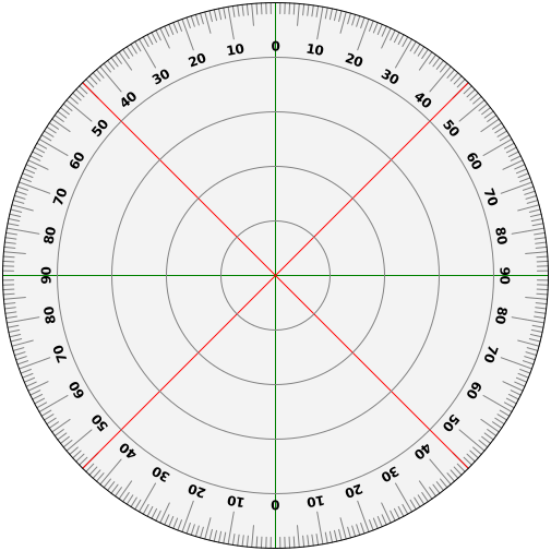
There ist a nice protractor.svg file on wikipedia. I use Inkscape to scale and print that.

You may also want to watch my video on this topic here.

Some woodworking

And the protractor
Pointer and tripod adapter
Next I need to put the ESP-12e module in AP-Mode, so it sends beacon packets. Then I wire it in a very basic configuration to run from a 3,7V lithium cell. To drop 0.6V, I put a 1N4148 in series with the module. (Actually, a 1N4148 a bit weak for the job. Go for a 1N4001 if you can. I couldn't find one in my parts bin.)
The TXD/RXD wires are still connected for programming
Can it get any simpler than that? GND and GPIO15 are connected to the negative terminal, VCC and CH_PD to the cathode of the 1N diode. The anode is connected to the positive terminal.
I use a 18650 cell and this holder.
No more unnecessary stuff
Test run
Now mount it all on a tripod and wait for a sunny day to take it all outside where we have little or no reflections.


Ok, let's go outside...


Results

I used LibreOffice to turn the handwritten values into a polar diagram. Here is the resulting  chart:


Although I didn't expect the field to be completely uniform, the result is pretty obvious:
The module (looked at from the component side, antenna pointing away from us) has a clear west-north-westernly preference and a clearly visible minimum at the opposite end. So you'll want that (upper left) corner of the module to point at your access point if you get near the edge of your wifi range.

ToDo

While working on this project, I found out about the ESP-12F, which supposedly has an improved antenna design over the ESP-12E. I do not have one here at the moment, but will compare the two if I can get hold of one.
To get a smoother chart, I should do two full rounds to smooth out the errors and do finer steps (5 instead of 10 degrees).


PS:

If you want to try the same, you don't need a Wifi tester. A PC with InSSIDer (the free 1.3.2.1 version), or even use another ESP-Module as WiFi scanner as shown here.

PPS: Shopping list:

Thin plywood, the size if an A4 paper
The protractor.svg file from wikipedia
A 18650 rechargeable battery. (Well, and a charger if you don't have one)
Suitable 18560 battery holder
One 1N4001 diode
and of course the ESP-12e module

Thursday, 10 December 2015

Espressif ESP-8266: minimal configuration for running the ESP-12e module

I am working on a project where I haven't quite decided on some of the details, so I wanted a module that breaks out a lot of the ESP8266's pins, just to have as many options available as possible.

Here is also a 5 minute video about it.

The ESP-12e module seems like a good choice, with the added benefit of having 4MBytes of flash memory.
ESP-12e module from Banggod
So I ordered a pack of three from Bangood for just under 8 Euros. After quite a long wait they arrived and I had to take them to the workbench for a quick test drive, right away.

Odd stuff

A few things are a bit odd about these modules:
  • The silkscreen is a very poor print quality
  • The ADC pin is labelled ADG
  • The GPIO labels are a mess. Eg: There is no GPIO0 (this is labelled GPIO6 instead)

Where's GPOI0?
Todo: try flashing LEDs on all GPIOs to compare against NodeMCUs IO table


Basic configuration

So after a little experimentation, this turned out the most basic configuration:
Basic config for ESP-12e
I plan to run this without a circuit board, so I'll simply shorten GPOI15 to ground and connect the "Chip Power Down" Pin (CH_PD) to 3.3V. 

The Module came preinstalled with some AT-firmware, I didn't much care about.

Flashing new firmware

To program new firmware, GPOI0 (which for some reason is GPIO6 here) needs to be connected to ground. I am a huge fan of NodeMCU, so I flashed that to the module.
Ground GPIO6 (=GPIO0) to flash firmware via UART

This goes without saying

Connecting the serial-usb converter is unspectacular. Just the usual RXD-TXD / TXD-RXD thing. And don't forget to connect the ground wires.
Connecting the USB2Serial converter


Wednesday, 25 November 2015

Using node.dsleep() in NodeMCU to extend battery lifetime in ESP8266 projects

For some applications, like checking sensors, the ESP8266 does not need to run permanently with all it's bells and whistles on. The datasheet claims 10uA when in deep sleep mode.
NodeMCU, currently my preferred firmware, does support that sleep mode, but I've never tried using it. Mainly because it is a pain to modify the ESP-01 which used to be my perferred module.

Olimex MOD-WIFI-ESP8266-DEV

With the Olimex modules, I aquired a while ago, trying this out is a piece of cake. Both the reset-pin and GPIO 16 are freely accessible. The ESP8266 wakes up from deep sleep on a falling edge on the reset pin. This signal does not necessarily need to come from GPIO16, but can also be generated externally.

The brown wire does it all

NodeMCU syntax

It is explained in detail here. Basically it is:

node.dsleep(Time-In-uSecs , option)

Where "option" can be 0-4. But I don't quite understand the "0" option yet.
If you send it to sleep for 0 useconds, you'll need to trigger the wakeup from an external source.

Power considerations

In my experiments, the running module took around 70mA from it's 3,3V supply.
In deep sleep mode, the module draws a little less than 0.8mA which is great and will run the system for months with a good 18650 rechargeable battery. Still it is quite a bit more than the 10uA from the data sheet.
Looking at the Olimex datasheet, two things come to mind:
  • The SPI Flash memory (W25Q16BVSSIG) has a 25-50 uA standby current and can peak to 25mA when active.
  • There is a power LED with a 2k resistor that is constantly on and will probably account for most of the current
Another interesting option to node.dsleep() ist option 4, which leaves WiFi disabled when waking up. This saves a lot of power while the system can read sensors or process other information. I've seen it draw around 12mA in this mode.

Video

I've also documented that in a short video on my youtube channel.

Todo

Try the same with an ESP-12 that has no LED

Saturday, 24 October 2015

Using the ESP8266 as a WiFi range extender

This blog article refers to my YouTube Video you find here.
It shows how an ESP8266 module (like this one) can be used as a (rather unreliable) WiFi range extender.

Overview of the setup

Beside an ESP8266 module, you need to:

  • download the modified firmeware here and flash it to your module 
  • copy the DNS forwarder script from here to your module
  • add a route to the 192.168.4.0 subnet to your default gateway (i.e. usually  your WiFi dsl/cable router)
  • attach the module to your WiFi network and run it in StationAP mode:
 wifi.setmode(wifi.STATIONAP)  
 wifi.sta.config("YOURSSID","YOURWIFIPASSWD")  
 tmr.alarm(0, 500, 1, function()  
     if wifi.sta.getip()==nil then  
      print("Connecting to AP...")  
     else  
      tmr.stop(1)  
      tmr.stop(0)  
      print("Connected as: " .. wifi.sta.getip())  
     end  
   end)  
 cfg={}  
    cfg.ssid="intarwebs"  
    wifi.ap.config(cfg)  

  • connect another device to the "intarwebs" SSID. If you want to really use that, you should encrypt that side as well. Here is how.
The disconnects from the Wifi Router appear to be related to  big packets and/or heavy traffic. It has been suggested that it might be a power issue, but neither with the scope, nor with the Fluke 87V's min/max function I was able to detected a significant voltage drop.
I have captured the traffic with wireshark, but could not make sense of it yet. My best guess at the moment is that with a big TCP windows size, the module runs into a buffer size problem or that it is busy for too long on the "left" side. The module only has one radio to serve both connections, so unlike your typical router, it can't forward a continuous stream of packets.


Wednesday, 23 September 2015

Generic UDP proxy for NodeMCU / ESP8266 - Simple LUA DNS proxy

For a project that has been in the works for quite some time, I need a ESP8266 module to act as a DNS proxy. Other than on my very popular CaptiveIntraweb project, that simply lies to all DNS requests, I need real DNS lookups this time.

Getting my head slowly around the event driven nature of NodeMCU, the code turned into a very compact, generic UDP proxy or forwarder.
The script is completely unaware of the structure of the data and could be used to proxy all sorts of UDP data.

Here is my code:

 -- Simple DNS Proxy  
 -- 20150923 by Andy Reischle  
 -- Blog: www.AReResearch.net  
 -- Vids: www.youtube.com/AReResearch  
 --  
 -- Uses googles dns server 8.8.8.8  
 -- change to whatever suits you  
 cu=net.createConnection(net.UDP,0)  
 cu:on("receive",function(cu,c)   
   -- print("Got a reply")  
   s:send(c)  
   end)  
 s=net.createServer(net.UDP)  
 s:on("receive",function(s,d)  
   -- print ("Got a request!")  
   cu:connect(53,"8.8.8.8")  
   cu:send(d)   
   end)  
 s:listen(53)  

The ESP-module is connected to a WiFi AP, of course. The IP address of the ESP module is 192.168.1.74 and will be different, depending on your home DHCP server.

I can query DNS information through the module now:
me@raspberrypi:~$ nslookup
> server 192.168.1.74
Default server: 192.168.1.74
Address: 192.168.1.74#53
> www.areresearch.net
Server:         192.168.1.74
Address:        192.168.1.74#53

Non-authoritative answer:
www.areresearch.net     canonical name = ghs.google.com.
ghs.google.com  canonical name = ghs.l.google.com.
Name:   ghs.l.google.com
Address: 173.194.65.121
>
The corresponding tcpdump also looks very clean:

me@raspberrypi:~$ sudo tcpdump -i eth0 port 53
tcpdump: verbose output suppressed, use -v or -vv for full protocol decode
listening on eth0, link-type EN10MB (Ethernet), capture size 65535 bytes
23:39:08.416736 IP noname.43027 > noname.domain: 56537+ A? www.areresearch.net. (37)
23:39:08.422009 IP noname.46122 > fritz.box.domain: 4560+ PTR? 58.1.168.192.in-addr.arpa. (43)
23:39:08.426857 IP fritz.box.domain > noname.46122: 4560* 1/0/0 PTR noname. (88)
23:39:08.428198 IP noname.45680 > fritz.box.domain: 56651+ PTR? 74.1.168.192.in-addr.arpa. (43)
23:39:08.430620 IP fritz.box.domain > noname.45680: 56651* 1/0/0 PTR noname. (88)
23:39:08.432969 IP noname.38314 > fritz.box.domain: 15794+ PTR? 1.1.168.192.in-addr.arpa. (42)
23:39:08.435987 IP fritz.box.domain > noname.38314: 15794* 1/0/0 PTR fritz.box. (89)
23:39:08.480105 IP noname.domain > noname.43027: 56537 3/0/0 CNAME ghs.google.com., CNAME ghs.l.google.com., A 173.194.65.121 (101)

While the rest of the project still requires a lot of tinkering, this little piece of the puzzle works nicely.